
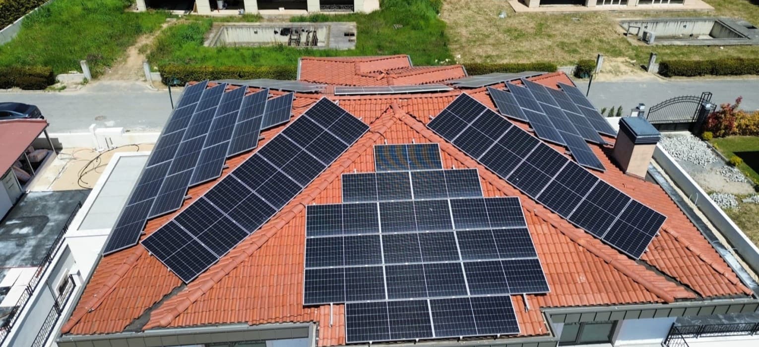
The mounting structure has to last as long as the panels. Material choice, wind and snow load, corrosion protection and watertight fixing details for roof and ground-mount systems.
The most visible part of a solar plant is the panels and the most discussed is the inverter, but what keeps the system standing for 25 years is the mounting structure. A badly designed mount works loose in the wind, lets water into the roof or rusts within a few years. Done right, it is never noticed. This article covers what matters in roof, facade and ground-mount work.
Load analysis: wind and snow
A mount is sized by wind and snow load far more than by self-weight. Wind depends on panel tilt, building height, the site wind speed and the panel's position on the roof (uplift is higher in edge and corner zones). Snow load is calculated to EN 1991-1-3 from the region and roof pitch. Ground plants also account for snow drifting behind the panels. The calculation drives both the profile section and the number of roof fixings.
Material and corrosion
Rails and clamps are usually aluminium alloy (typically EN AW-6005A); the sub-structure steel is hot-dip galvanised (EN ISO 1461) or zinc-aluminium-magnesium coated sheet such as Magnelis. Bolts, nuts and washers are A2 stainless, or A4 on coastal sites. Where dissimilar metals meet there is a galvanic corrosion risk, so an isolating washer or a suitable coating is used between aluminium and carbon steel. On coastal and industrial-atmosphere sites the coating class is stepped up.
Fixing by roof type
- Tiled roof: a rafter hook is fixed to the rafter and the tile is lifted and re-seated; the water path is not disturbed.
- Trapezoidal sheet roof: fixed to the purlin with a calibrated seal and an EPDM-washered screw; the hole is sealed by the washer.
- Sandwich panel roof: load is carried into the structure below the panel, not just into the outer skin.
- Concrete roof: chemical anchors or a ballasted system; the membrane stays intact.
Ground-mount structures
On ground plants the structure sits on driven steel piles, screw piles or concrete footings; a soil survey and a pull-out test set the pile length. Fixed-tilt tables are the most common solution; single-axis trackers raise yield but add mechanical maintenance. The clearance from the ground to the lower panel edge is chosen against snow build-up and shading from vegetation.
Earthing and equipotential bonding
The whole metal structure is bonded to the equipotential bar; rail splices and clamps are made continuous with self-tapping earthing washers or a separate conductor. Where a lightning protection system exists, the mount is positioned to respect its separation distance. This detail is often left to last, yet the panel warranty and electrical safety depend on it directly.
In short
A good mount is invisible: it does not move in the wind, does not leak the roof, does not rust and does not put the panel warranty at risk. That takes a site-specific load calculation, material and fixings chosen in the same corrosion class, and a roof detail solved together with the waterproofing. ÇelikÇ designs, fabricates and erects the mounting structure for roof and ground-mount solar projects.